상품 이미지 전체보기
제품 정보
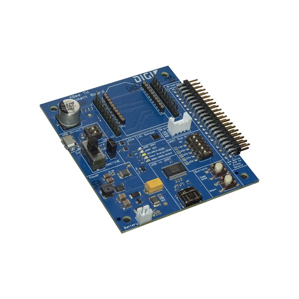
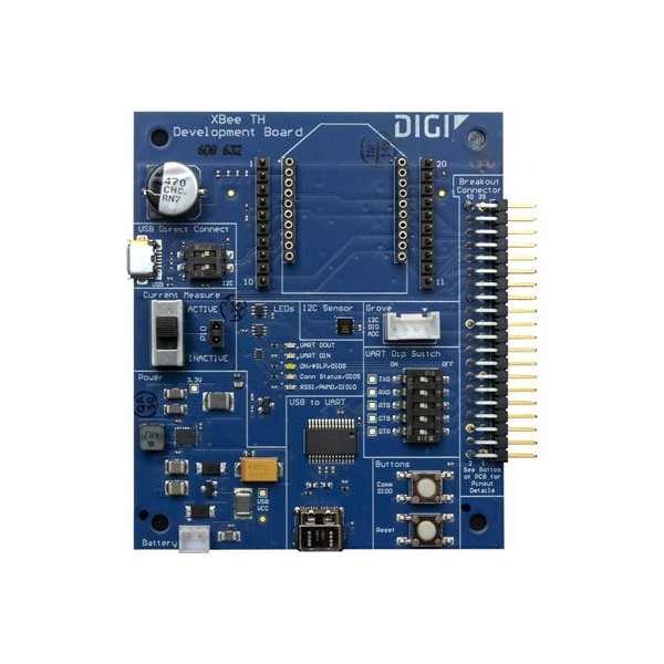
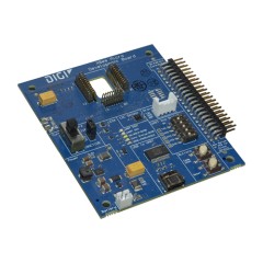
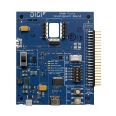
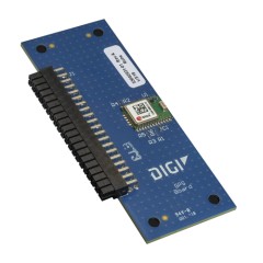
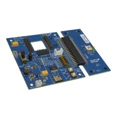
Digi XBIB-C 개발 보드
개발 컨셉 작업 및 테스트 시간을 단축시킬 수 있는 개발 회로 보드
제품 특징
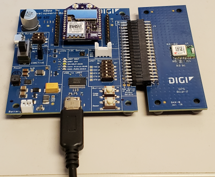
Over View
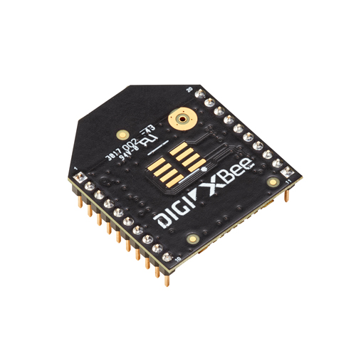
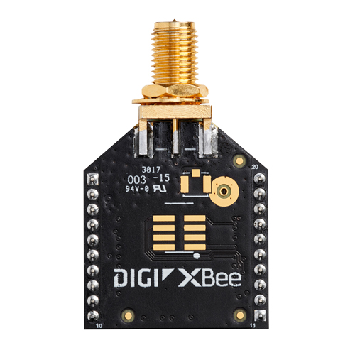
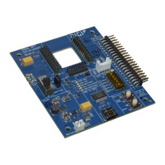
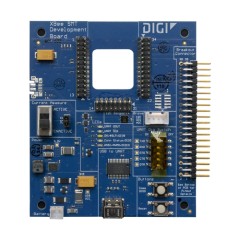
무선 모듈의 특징과 기능을 평가하는 것은 어려울 수 있습니다. 대부분의 무선 모듈은 다양한 기능을 가지고 있기 때문에 일반 개발 보드는 무선 모듈의 완전한 기능을 제대로 보여줄 수 있는 기능을 갖추고 있지 않습니다. 새로운 Digi XBIB-C 개발 보드를 통해 Digi XBee® 모듈의 모든 기능을 쉽게 평가할 수 있습니다. 개발 보드는 Through-hole, Surface-mount 및 Micro-mount 등 모든 모듈에 대응할 수 있도록 3가지 모델로 출시되었습니다.
XBee셀룰러 모뎀을 사용할 경우, 보드는 개발자들이 셀룰러 모뎀과 직접 상호작용을 할 수 있도록 USB 다이렉트 포트를 갖추고 있습니다. 또한 이 보드는 Digi XBee 모듈이 MicroPython을 사용하여 I2C 프로토콜과 어떻게 인터페이스할 수 있는지를 쉽게 확인할 수 있도록 온도 및 습도 센서를 보유하고 있습니다.
배터리 구동 애플리케이션의 경우, 개발자가 모듈의 배터리 소비량을 신속하게 평가할 수 있는 전류 모니터 헤더를 가지고 있습니다. 단순히 핀에 전압계를 연결함으로써 모듈이 얼마나 많은 전류를 소모하는지 계산할 수 있으므로 개발자는 특정 용도에 대한 배터리 속성을 결정할 수 있습니다.
또한 보드에는 다른 브레이크 아웃 기능이 포함되어 있습니다. 예를 들어, 보드는 그루브 커넥터를 가지고 있다. 이 그루브 커넥터는 보드가 개발 상태 및 성능의 증명을 위해 그루브 센서 및 제품과 인터페이스할 수 있도록 합니다. 그루브 커넥터 외에도, 보드는 Digi XBee 모듈에 대한 모든 보드의 인터페이스를 만들 수 있는 40핀 헤더를 가지고 있습니다.
Reference
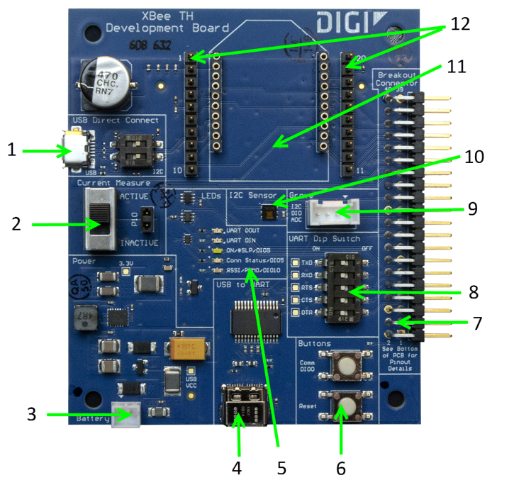
Number |
Item |
Description |
|---|---|---|
|
1 |
Secondary USB (USB MICRO B) and DIP Switch |
Secondary USB Connector for direct programming of modules on some XBee units. Flip the Dip switches to the right for I2C access to the board; flip Dip switches to the left to disable I2C access to the board. The USB_P and USB_N lines are always connected to the XBee, regardless of Dip switch setting. This USB port is not designed to power the module or the board. Do not plug in a USB cable here unless the board is already being powered through the main USB-C connector. Do not attach a USB cable here if the Dip switches are pushed to the right. |
|
WARNING! Direct input of USB lines into XBee units or I2C lines not designed to handle 5V can result in the destruction of the XBee or I2C components. Could cause fire or serious injury. Do not plug in a USB cable here if the XBee device is not designed for it and do not plug in a USB cable here if the Dip switches are pushed to the right. |
||
|
2 |
Current Measure |
Large switch controls whether current measure mode is active or inactive. When inactive, current can freely flow to the VCC pin of the XBee. When active, the VCC pin of the XBee is disconnected from the 3.3 V line on the development board. This allows current measurement to be conducted by attaching a current meter across the jumper P10. |
|
3 |
Battery Connector |
If desired, a battery can be attached to provide power to the development board. The voltage can range from 2 V to 5 V. The positive terminal is on the left. If the USB-C connector is connected to a computer, the power will be provided through the USB-C connector and not the battery connector. |
|
4 |
USB-C Connector |
Connects to your computer and provides the power for the development board. This is connected to a USB to UART conversion chip that has the five UART lines passed to the XBee. The UART Dip Switch can be used to disconnect these UART lines from the XBee. |
|
5 |
LED indicator |
Red: UART DOUT (modem sending serial/UART data to host) Green: UART DIN (modem receiving serial/UART data from host) White: ON/SLP/DIO9 Blue: Connection Status/DIO5 Yellow: RSSI/PWM0/DIO10 |
|
6 |
User Buttons |
Comm DIO0 Button connects the Commissioning/DIO0 pin on the XBee Connector through to a 10 Ω resistor to GND when pressed.
RESET Button Connects to the RESET pin on the XBee Connector to GND when pressed. |
|
7 |
Breakout Connector |
This 40 pin connector can be used to connect to various XBee pins as shown on the silkscreen on the bottom of the board. |
|
8 |
UART Dip Switch |
This dip switch allows the user to disconnect any of the primary UART lines on the XBee from the USB to UART conversion chip. This allows for testing on the primary UART lines without the USB to UART conversion chip interfering. Push Dip switches to the right to disconnect the USB to UART conversion chip from the XBee. |
|
9 |
Grove Connector |
This connector can be used to attach I2C enabled devices to the development board. Note that I2C needs to be available on the XBee in the board for this functionality to be used. Pin 1: I2C_CLK/XBee DIO1 Pin2: I2C_SDA/XBee DIO11 Pin3: VCC Pin4: GND |
|
10 |
Temp/Humidity Sensor |
This as a Texas Instruments HDC1080 temperature and humidity sensor. This part is accessible through I2C. Be sure that the XBee that is inserted into the development board has I2C if access to this sensor is desired. |
|
11 |
XBee Socket |
This is the socket for the XBee (TH form factor). |
|
12 |
XBee Test Point Pins |
Allows easy access for probes for all 20 XBee TH pins. Pin 1 is shorted to Pin 1 on the XBee and so on. |
· 제품 필수 상세정보
| 품명 | 상품페이지 참고 |
|---|---|
| 모델명 | 상품페이지 참고 |
| 법에 의한 인증·허가 등을 받았음을 확인할 수 있는 경우 그에 대한 사항 | 상품페이지 참고 |
| 제조국 또는 원산지 | 상품페이지 참고 |
| 제조자 | 상품페이지 참고 |
| A/S 책임자와 전화번호 또는 소비자상담 관련 전화번호 | 상품페이지 참고 |
관련 제품
· 주문 정보
-
XBIB-C-SMT
137,500원 -
XBIB-C-MMT
137,500원 -
XBIB-C-GPS
전화문의
제품 자료
구매후기
등록된 구매후기
구매후기가 없습니다.

